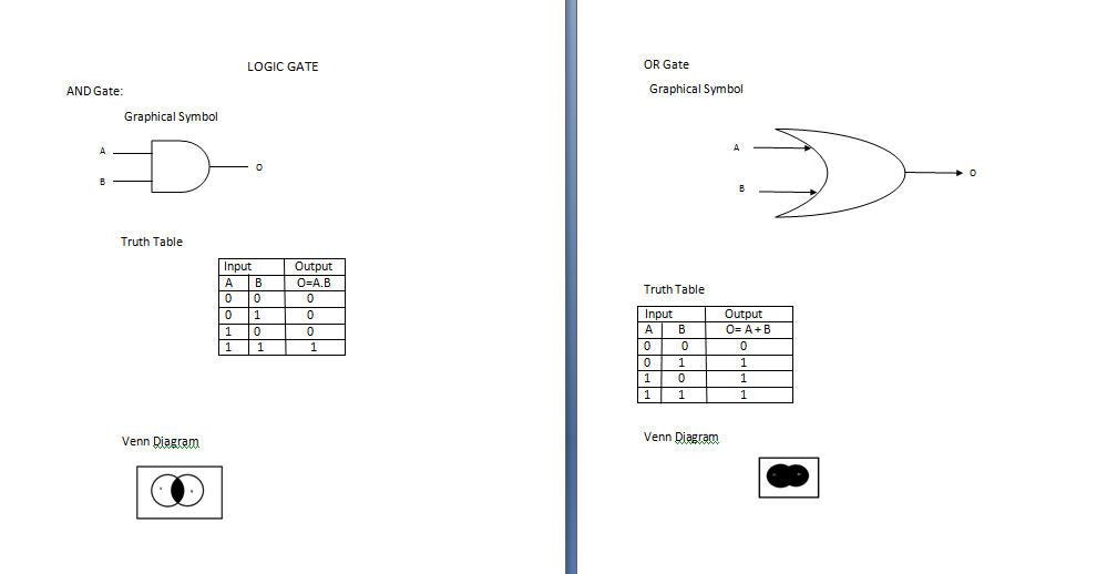
LOGIC GATE


 LOGIC GATE
AND Gate:
                    Graphical Symbol
O
 
B
 
A


                   Truth Table
Input               Output
A        B            O=A.B
0        0                0
0        1                0
1        0                0   
1         1                1    


                     Venn Diagram
Untitled.png

OR Gate
  Graphical Symbol


Truth Table
 Input                  Output
 A         B              O= A + B
0           0                  0
0          1                   1
1          0                   1
1          1                   1

Venn Diagram OR GATE.png


NOT Gate
        Graphical Symbol
A


Truth Table
Input
Output
A
O=A’
0
1
1
0

Venn Diagram

NOT Gate.pngTruth Table
Input
Output
A             B
O=(A.B)’
0             0
1
0             1
1
1             0
1
1             1
0

Venn DiagramNAND GATE.png
NOR Gate
O
 
A
 
B
 
       Graphical Symbol


Input
Output
A             B
O=(A+B)’
0              0
1
0              1
0
1              0
0
1              1
0
Truth Table


NAND Gate
           Graphical Symbol
 
https://drive.google.com/open?id=1ISY-wi5dE5_kRahy-73KiTpDqLVdnHlA https://drive.google.com/open?id=1n5comNl-UrQjhjl9Blw00NUer7albkaD https://drive.google.com/open?id=1acuv4yYKF8dUY5jLP1s_dp3dodKwkgqz https://drive.google.com/open?id=1fqrehAJTf_ROCjKsKWQ72oc1DH-ne9B3
Venn Diagram

NOR gate.png
X-OR Gate
A
 
B
 
O
 
      Graphical Symbol


Truth Table
Input
Output
A                  B
O=(A+B)
0                  0
0
0                  1  
1
1                  0     
1
1                  1 
0


Venn Diagram
ALL GATE.png

X-NOR Gate
     Graphical Symbol
A
 
B
 
A


Truth Table
Input
Output
A
B
O=(A+B)’
0
0
1
0
1
0
1
0
0
1
1
1

Venn Diagram
ALL GATE.png

Comments

Popular posts from this blog

CERTIFICATE

TITLE PAGE

COVER PAGE